: Mid Plane Design Method")
Konichiwa, SolidWorks ninjas. Welcome to the dojo (Designing Objects Journeymen Organization). Let’s flip roll right into our training regime.
Mid Plane Is Your Symmetrical Friend
As we take our 2D sketches from the flat world into the third Extruded Boss/Base Feature dimension we have options. Some options utilize references as drivers. When not using reference drivers but creating stand-alone geometry, I default to the Mid Plane option over the Blind option. Particularly, when the shape created will serve as starting geometry that is built off (and/or is) the primary geometric volume.
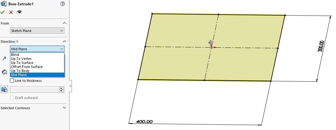
Why Design Using Midplanes?
A Mid Plane extrude creates part symmetry about a plane using one feature. Symmetry can be utilized for elegant modeling but also leveraged and built upon using, for example, mirror options. Midplanes can also be very useful for mating, as center-to-center mates are common in the best practice’s universe.
I often go one step further, adding reference planes on the flat face of 3D geometry. One can mate to a plane or a face and one can create a sketch on a plane or a face, so why add extra work, steps, and features to create planes when existing faces serve the same purposes?
If there is a design parameter where the distance or relative distance is a known variable, referencing a plane locks it in stone from a digital perspective. When it comes to all aspects of design, moving the unknown variables to the known variables column (and keeping them there) is the path to victory.
Faces change in the process of finishing design elements and this has a cascading effect. When modifying a face it doesn’t leave the original reference and add new reference options, it becomes a new reference and the original reference is erased from our shared universal consciousness.
Think of a plane like a wall of your home, away from which you have other objects, like your couch set to a specific distance. One could use the backside of a painting mounted to that wall as the reference instead, as it is the same distance. But this assumes you never change your taste in velvet blacklight posters.
So, remember this simple mnemonic rhyme: “Faces can erases but planes remain!”
Midplane Design Method in Action: Sheet Metal Mid Plane
This Mid Plane Design Method for mirroring, mating, and overall elegance philosophy holds just as true (or truer) for sheet metal parts. So let’s try it out.
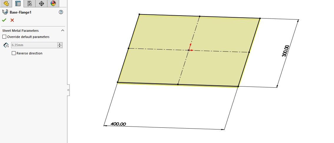
Sacré bleu! All there is to choose from is a thickness one way or the other! It’s impossible to have a midplane in sheet metal. The All-Wise SOLIDWORKS Guru That Sits Atop The Eternal Mountain Top® has deemed it shall not be so and so it shall NOT be!

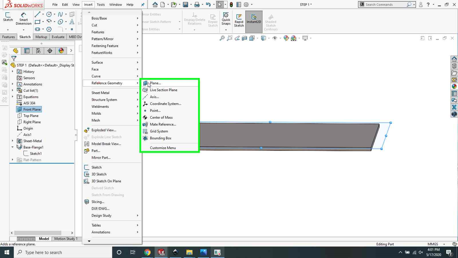
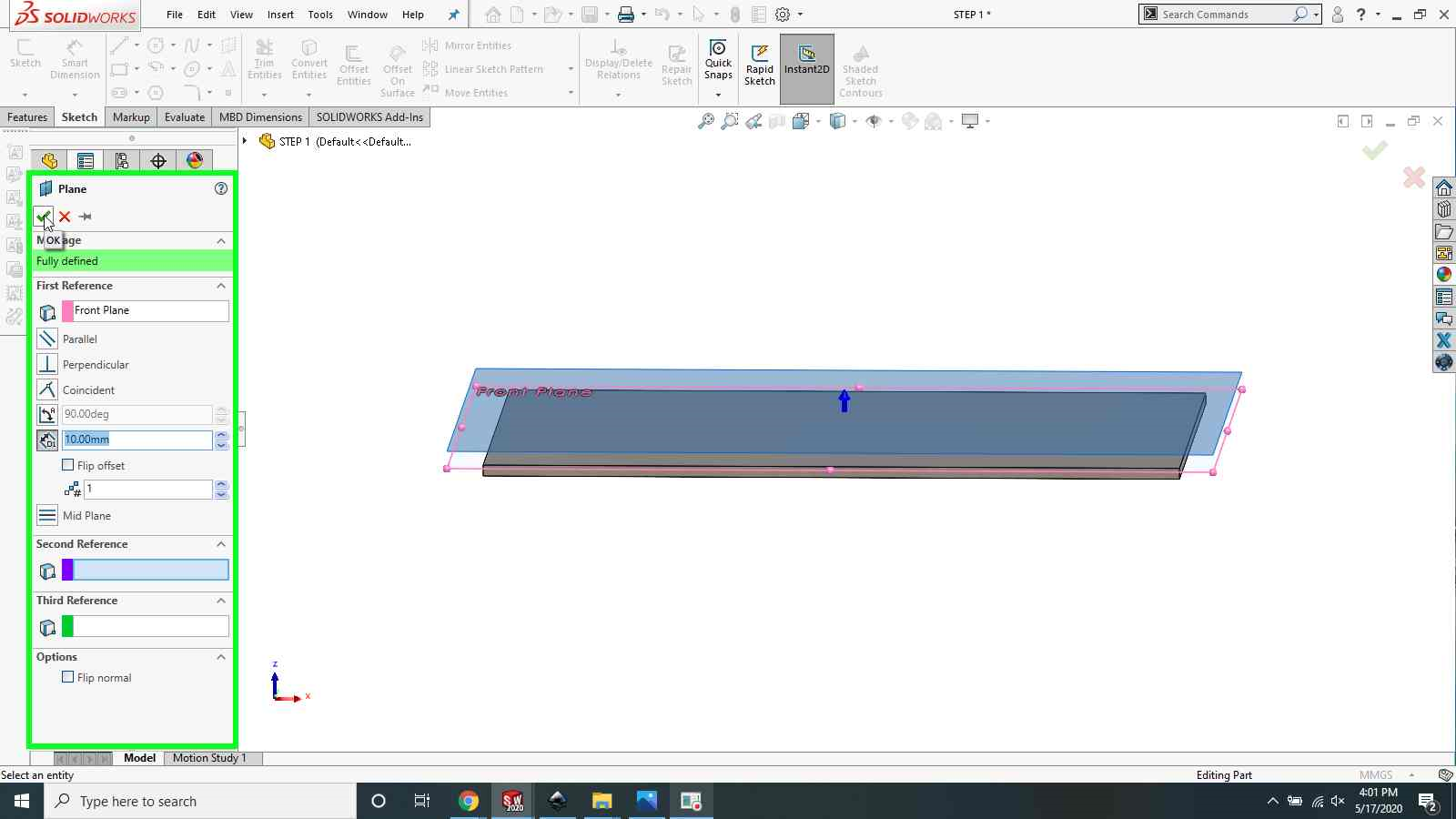
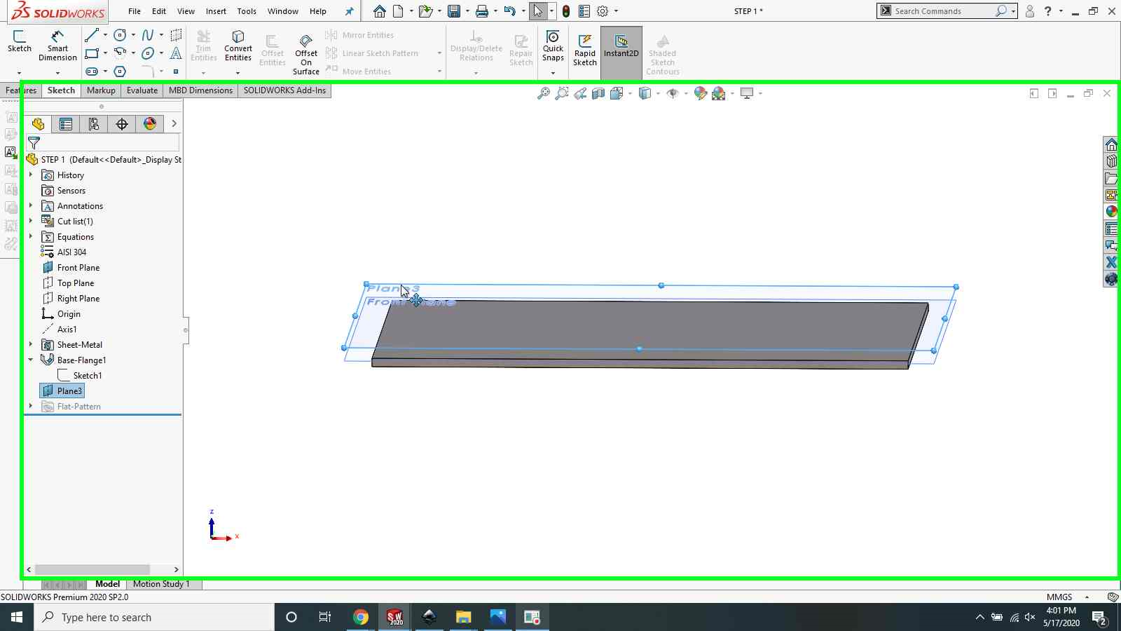
STEP 1: Create An Offset Plane
Create a new plane using the Front Plane as the reference (or the plane you used to sketch the sheet metal Base Flange sketch. The plane should be offset from the sheet metal. The offset distances will be changed later, so pick a distance to start so it’s easily differentiated and selected. Hit OK (the green check).
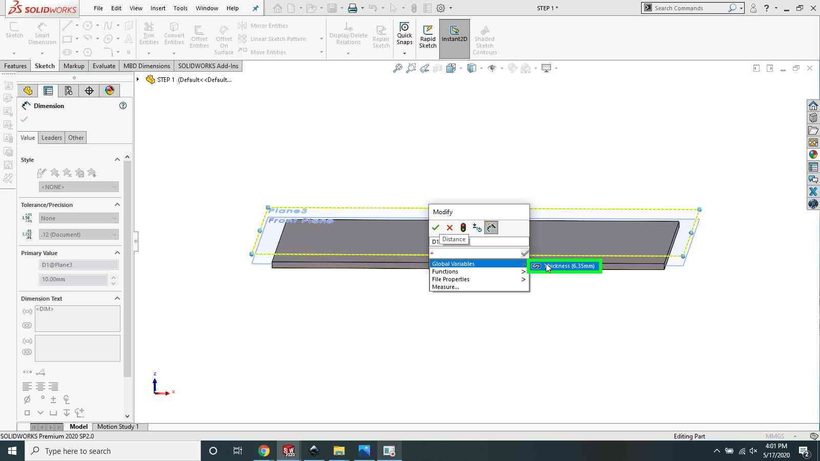
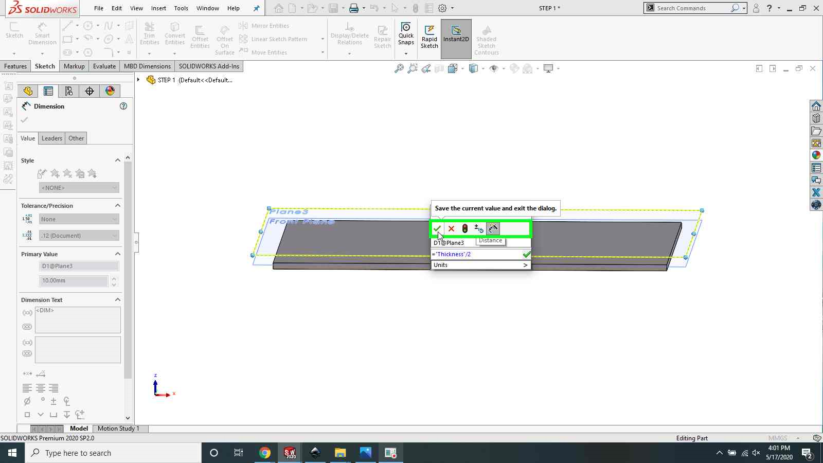
STEP 2: Use Global Variable to Drive the Offset Dimension
Select the plane created in STEP 1 to show the offset dimension, then double-click the offset dimension to activate the Modify Dialog Box. In the Modify Dialog Box type “=”, then hover the mouse over the Global Variables selection tab and select Thickness. Complete the equation to =”Thickness”/2. Save your equation and exit the Modify Dialog Box and the Dimensions Dialog Box. The plane is now offset half the thickness of the sheet metal.

STEP 3: Center the Sheet Metal Body
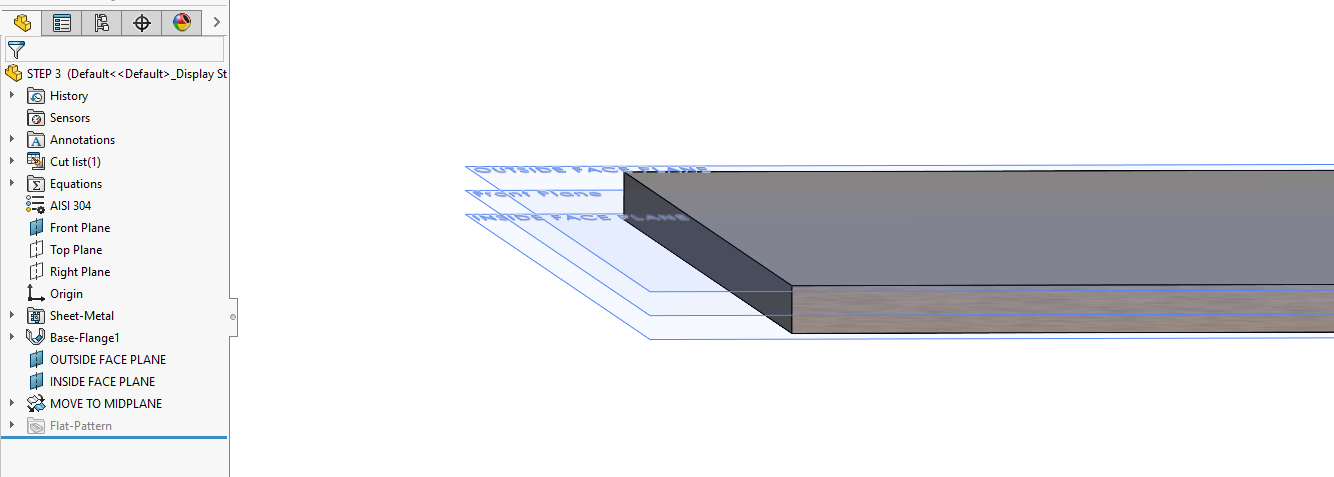
Select the Move/Copy Bodies Feature (Insert > Features > Move/Copy). With the Bodies to Move dialog activated/highlighted, select the sheet metal body in the Graphics Area. Click select the Coincident mate button option. Single-click the Mate Settings dialog to activate/highlight, select the offset plane and then select the nearest parallel face of the sheet metal body in the Graphics Area. The sheet metal body will move to snap the face and plane together.
The origin plane is now in the center (or middle) of your part, effectively making it a middle or “midplane”. I recommend repeating steps 1 and 2 in the opposite direction as the first plane to create a mating plane for the opposite sheet metal face. Finally, give the features new names to indicate the design intent. Your future self/coworkers will thank you.
STEP 4: Save As a Part Template
Now, save the part file as a Part Template (.prtdot) so it can be used to create sheet metal parts in the future to save time when the “Midplane Design Method” is needed.
A More Robust Methodology
The Midplane Design Method is very robust. It works for sheet metal just as it does for other sheet metal-like parts (wood panels, aluminum honeycomb, etc). If one decides to change the thickness of your sheet metal, the midplane will automatically update accordingly.
When Would You Move/Change a Face?
Allow me to provide some practical examples of design reasons where one might want to change a face. Sometimes I use the Cut Thicken / Boss Thicken features to remove and then add back a thin shell of material to represent a coating. The most common example of face modification is when using the Split Line feature. The Split Line feature is a useful tool for adding information to the part without changing the overall 3D geometry. For example, Split Line can be used to show graphics that are screen printed on the part or apply helpful information that won’t be on the actual part (like grain direction). The Split Line feature is also a powerful tool to create temporary reference geometry on surfaces (usually curved) that aid feature creation and modeling. The Split Line feature can also be used to create a face to represent structural loading or constraints faces for Finite Element Analysis. The list goes on and on.
We don’t want to get fancy for fancy’s sake. We want to be elegant for efficiency’s sake.
Complex problems may require complex solutions and we rely on Computer-Aided Design and Computer-Aided Engineering. The digital details we are managing grow exponentially with complexity and it becomes impossible to mentally manage all the interactions at once. Things can start to get unwieldy; details get lost and things quickly can become overwhelming. We don’t want to get fancy for fancy’s sake. We want to be elegant for efficiency’s sake. We don’t want to miss out on the opportunity to use helpful features or communicate information because we can’t manage these digital interactions and consequently have fewer solutions. Lock-in design intent when it is certain and create better foundations to build upon. It is like paying for things in full as you go instead of accruing a mountain of debt you can’t pay off, and then not having nice things.
So as it turns out, the All-Wise SOLIDWORKS Guru That Sits Atop The Eternal Mountain Top® (A.W.SW.G.T.S.A.T.E.M.T) is me! And I do what I want! If you have a question for the A.W.SW.G.T.S.A.T.E.M.T or if you want to try to stump me, put your question in the comments below.