In this video tutorial, I offer up a brief modeling tutorial on how to use the engineering draft feature inside PTC Creo Parametric modeling software.
Last time I touched on the fundamentals of draft angle, especially when designing objects that will be mass-produced using injection molding, casting, or other forming processes. Our illustrious subject will be the good ‘ole no frills trash can. They come in all shapes, sizes and materials. The one thing they all have in common: draft.

When it comes to 3D modeling packages, Creo Parametric contains a suite of tools that are wide and deep. The Draft Feature within itself has the flexibility to achieve basic draft such as in our tutorial today or complex, curve-driven split draft.

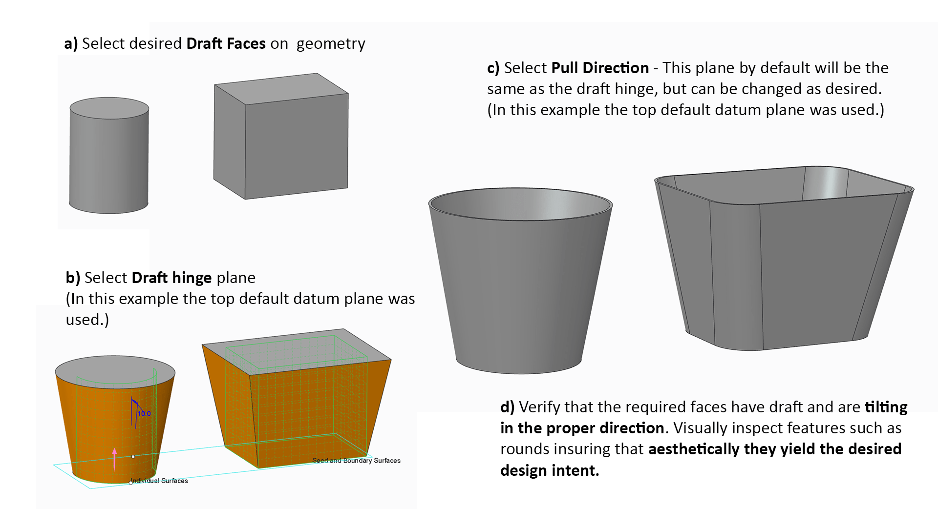
Only three inputs are needed to successfully create a draft feature: 1) Draft Surfaces, 2) Draft Hinges, and 3) Pull Direction. Pick’em right and you’re in business.
So, without further ado, feel free to dive into the video.
In summary, the steps to create draft using the Creo Parametric basic draft are depicted in this final image.